Table of Contents
Key Takeaways
- Improper installation causes 45% of softener valve failures within two years
- Following proper procedures extends valve life by 60% and reduces maintenance by USD 2,000-5,000 annually
- Industrial installations require 20-30% higher flow rates than residential, demanding reinforced components
- Bypass configuration prevents process interruptions and enables 75% faster repairs
- ChiMay's industrial valves support 1 to 30 m³/h, from commercial to large industrial applications
Introduction
Water softener valves govern regeneration cycles maintaining resin effectiveness. The industrial softener market exceeds USD 2.4 billion, yet 45% of failures trace to installation deficiencies.
Step 1: Site Assessment and Preparation
Structural Requirements
Industrial softener systems weigh 500-2,000 kg when filled. Floor structures must support loads without settlement.
Clearance Requirements:
- Front clearance: Minimum 1 meter for control head access
- Side clearance: 0.5 meters for piping connections
- Top clearance: 0.75 meters for resin loading
Drainage Provisions
- Floor drains: Handle peak backwash flow (50-150 L/min)
- Overflow drains: Handle combined flow from multiple vessels
- Backflow prevention: Install air gaps per plumbing codes
Step 2: Piping System Design
Pipe Sizing
Calculate based on peak demand: Qpeak = Qaverage × Peak Factor (typically 1.5-2.5 for industrial)
Total system pressure drop should not exceed 0.5-1.0 bar.
Pipe Material Selection
| Material | Advantages | Best Applications |
|---|---|---|
| PVC/CPVC | Low cost, chemical resistance | Secondary systems |
| Stainless Steel 316L | High strength, corrosion resistance | High temperature, critical |
| HDPE | Flexibility, chemical resistance | Buried piping |
Step 3: Valve Installation
Orientation
Industrial valves are designed for vertical (top-mount) installation with control valve on mineral tank top.
Brine Tank Positioning
- Position minimum 12 inches below softener valve
- Locate within 3 meters of valve for reliable brine injection
- Ensure unobstructed top access for salt loading
Step 4: Electrical Installation
Power Requirements
- Timer/Control: 24 VAC from Class 2 transformer
- Drive Motor: 115 VAC or 24 VDC
- Auxiliary: Solenoid valves, indicators, communication
Wiring Best Practices
- Use appropriately sized conduit for environment
- Maintain separation from power wiring
- Verify ground resistance <25 ohms
Step 5: Initial Startup
Pre-Startup Inspection
- All connections properly torqued and sealed
- Drain lines clear and properly sized
- Electrical connections secure
- Control valve in bypass position
- Inlet water valve closed
- Salt loaded in brine tank
Initial Backwash
- Slowly open inlet with valve in bypass
- Allow vessel fill, bleed air through top
- Transition to backwash position
- Backwash for 10-15 minutes until clear
- Verify drain flow rate
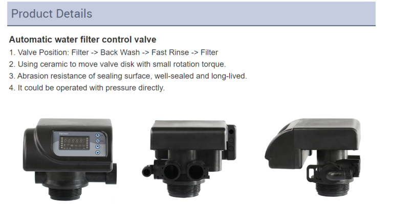
Step 6: Control Configuration
Key Parameters
| Parameter | Typical Range | Notes |
|---|---|---|
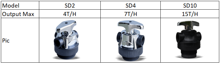
| Service Flow Rate | 1-30 m³/h | Set to design capacity |
| Capacity per Cycle | 50-500 m³/degree | Based on resin volume |
| Regeneration Trigger | Volume or time | Volume preferred |
| Backwash Duration | 10-20 minutes | Adjust for temperature |
| Brine Draw Time | 30-90 minutes | Based on tank height |
Step 7: System Integration
PLC Integration
- Hardwired signals: Regeneration initiation, alarm output, remote start
- Network integration: Modbus registers, diagnostics, remote configuration
SCADA Integration
- Real-time monitoring: Flow rates, pressure, status
- Alarm management: Automatic alerting
- Historical logging: Trend analysis
Step 8: Maintenance Planning
Maintenance Schedule
| Task | Frequency | Responsible |
|---|---|---|
| Salt level check | Weekly | Operations |
| Salt refill | Monthly | Operations |
| Salt bridge inspection | Quarterly | Maintenance |
| Injector cleaning | Semi-annually | Maintenance |
| Full valve service | Annually | Technician |
| Control rebuild | Every 3-5 years | Service |
Conclusion
Proper installation requires attention to eight critical steps. The 45% failure rate from installation deficiencies underscores the importance of established procedures.
ChiMay's industrial valves combine robust construction with advanced control capabilities. Following installation best practices achieves 60% improvement in service life and USD 2,000-5,000 annual maintenance savings.