Table of Contents
The Complete Guide to Sanitary Water Sensor Installation
Key Takeaways:
– Sanitary installation ensures sensor performance and prevents contamination risks in pharmaceutical water systems
– Proper placement, orientation, and connection design maximize measurement reliability
– Regulatory inspections specifically examine sensor installation practices
– Complete documentation of installation validates compliance throughout system lifecycle
Installing water quality sensors in pharmaceutical applications demands attention to details that determine whether your monitoring program succeeds during regulatory inspection. This guide covers everything you need to know about installing sensors that satisfy both operational and regulatory requirements.
Why Sanitary Installation Matters
When FDA inspectors evaluate pharmaceutical water systems, sensor installation practices receive scrutiny that reflects their importance to product quality. Inspectors verify that sensors meet material and surface finish specifications, examine installation orientation and connection design, and review calibration records.
Industry data indicates that installation-related issues account for approximately 30% of pharmaceutical water sensor problems, making installation quality a critical success factor.
Understanding Sanitary Requirements
Material Specifications
316L Stainless Steel: The standard material for pharmaceutical water system components—excellent corrosion resistance, capable of achieving Ra ≤ 0.8 μm surface finish, compatible with sanitization temperatures.
Sealing Materials: Elastomer seals must meet FDA 21 CFR 177.2600 requirements, USP Class VI certification, and temperature/chemical compatibility.
Surface Finish Requirements
The internal surfaces of pharmaceutical water sensors must achieve Ra ≤ 0.8 μm—smooth enough to prevent microbial adhesion, rough enough to allow proper cleaning.
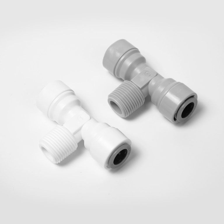
Connection Standards
Pharmaceutical water sensors employ standardized connections ensuring interchangeability, cleanability, and leak-free operation:
| Connection Type | Application | Advantages |
|---|---|---|
| Tri-clamp | Most common | Easy removal, standardized |
| DIN 11851 | European standard | Threaded security |
| SMS | Scandinavian standard | Robust connection |
Shanghai ChiMay sensors employ 316L stainless steel construction with FDA-compliant EPDM or PTFE seals, meeting pharmaceutical requirements.
Sensor Placement Strategy
Critical Control Points
Storage Tank Monitoring: Position sensors at tank outlet, minimum submergence level, away from walls where stratification may occur.
Distribution Loop Monitoring: Loop sensors provide system-wide quality indication—comparison with storage tank indicates distribution performance.
Point-of-Use Monitoring: Selected outlets represent critical applications—high-volume dispensing, extended water contact, final product preparation.
Location Assessment Criteria
- Adequate straight pipe runs (5 diameters downstream, 3 upstream)
- Orientation preventing air bubble accumulation
- Accessibility for maintenance
- Appropriate environmental conditions
Installation Orientation
The Impact of Orientation
Preferred: Pointing Downward — Air bubbles rise away from measurement zone, particles cannot accumulate, gravity assists drainage.
Acceptable: Horizontal — Requires careful bubble management, may need increased maintenance frequency.
Avoid: Pointing Upward — Air bubbles accumulate, particles settle, causes erratic readings and calibration drift.
Process Connection Design
Tri-Clamp Installation
- Inspect all components for damage or contamination
- Verify gasket material compatibility
- Position gasket on ferrule face
- Align sensor with gasket
- Install clamp and hand-tighten
- Torque evenly to specification
| Tri-clamp Size | Torque Value |
|---|---|
| 1” – 1.5” | 5-10 N·m |
| 2” – 3” | 10-15 N·m |
Instrument Valves
Instrument valves enable sensor isolation for maintenance without draining the system.
Temperature Considerations
Sanitization Effects
SIP (Steam-in-Place) conditions require specific consideration:
| Parameter | Maximum Temperature | Maximum Duration |
|---|---|---|
| Typical sensors | 130°C | 60 minutes |
| High-temp sensors | 150°C | 30 minutes |
Electrical Installation
Signal Cabling
Proper cable selection ensures signal integrity—shielded cable prevents electrical interference, proper gauge prevents voltage drop.
| Signal Type | Typical Maximum Length |
|---|---|
| 4-20mA (passive) | 1000 meters |
| HART | 1000 meters |
| Modbus RS-485 | 1200 meters |
Documentation Requirements
Installation Qualification Records
Each sensor installation requires documentation of component specifications, installation date and personnel, connection type, orientation verification, and initial calibration results.
As-Built Documentation
Maintain current documentation reflecting actual installation—sensor location, updated drawings, sensor history, deviation records.
Common Installation Mistakes
Inadequate Straight Pipe Runs: Causes turbulent flow affecting measurement accuracy.
Upward-Facing Sensors: Accumulate air and particles, causing erratic readings.
Dead Leg Creation: Creates stagnant zones with biofilm formation risk.
Improper Torquing: Causes leaks from under-tightening or gasket damage from over-tightening.
Inadequate Documentation: Creates compliance gaps during inspections.
Conclusion
Sanitary water sensor installation demands attention to material and surface finish requirements, strategic placement, proper orientation, and methodical documentation. When FDA inspectors examine your sensor installations, well-documented, properly installed sensors demonstrate operational excellence.
Shanghai ChiMay provides not only sensors meeting pharmaceutical requirements but also installation guidance and documentation support. Our comprehensive approach combines reliable sensors, practical expertise, and documentation resources enabling successful regulatory outcomes.